The short version
This coil did not fail because induction is mysterious. It failed because insulation position, concentrator clearance, and final verification were not controlled in the area where failure was most likely to start.
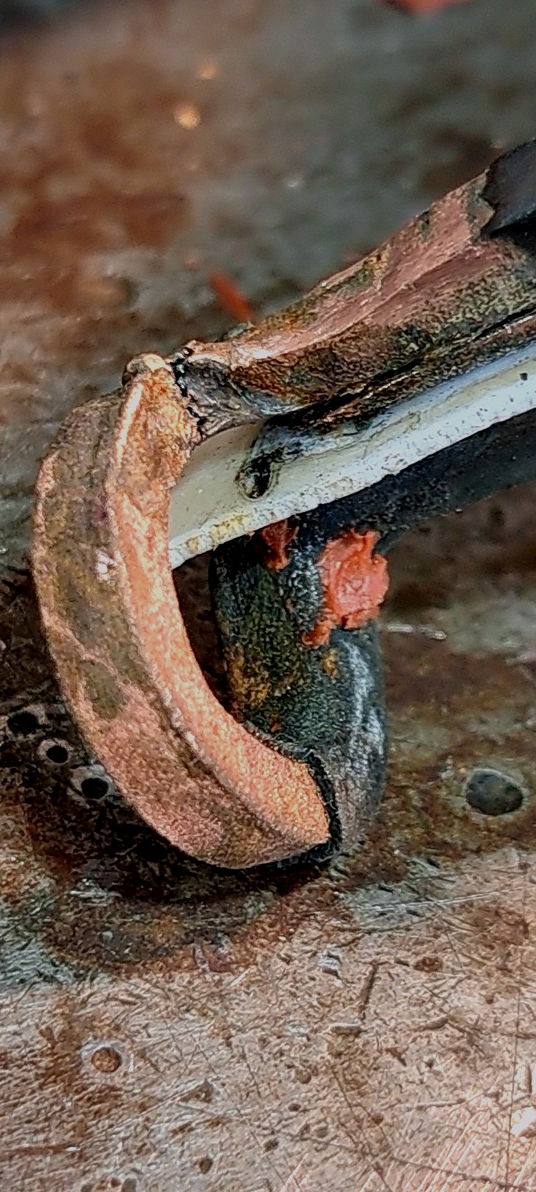
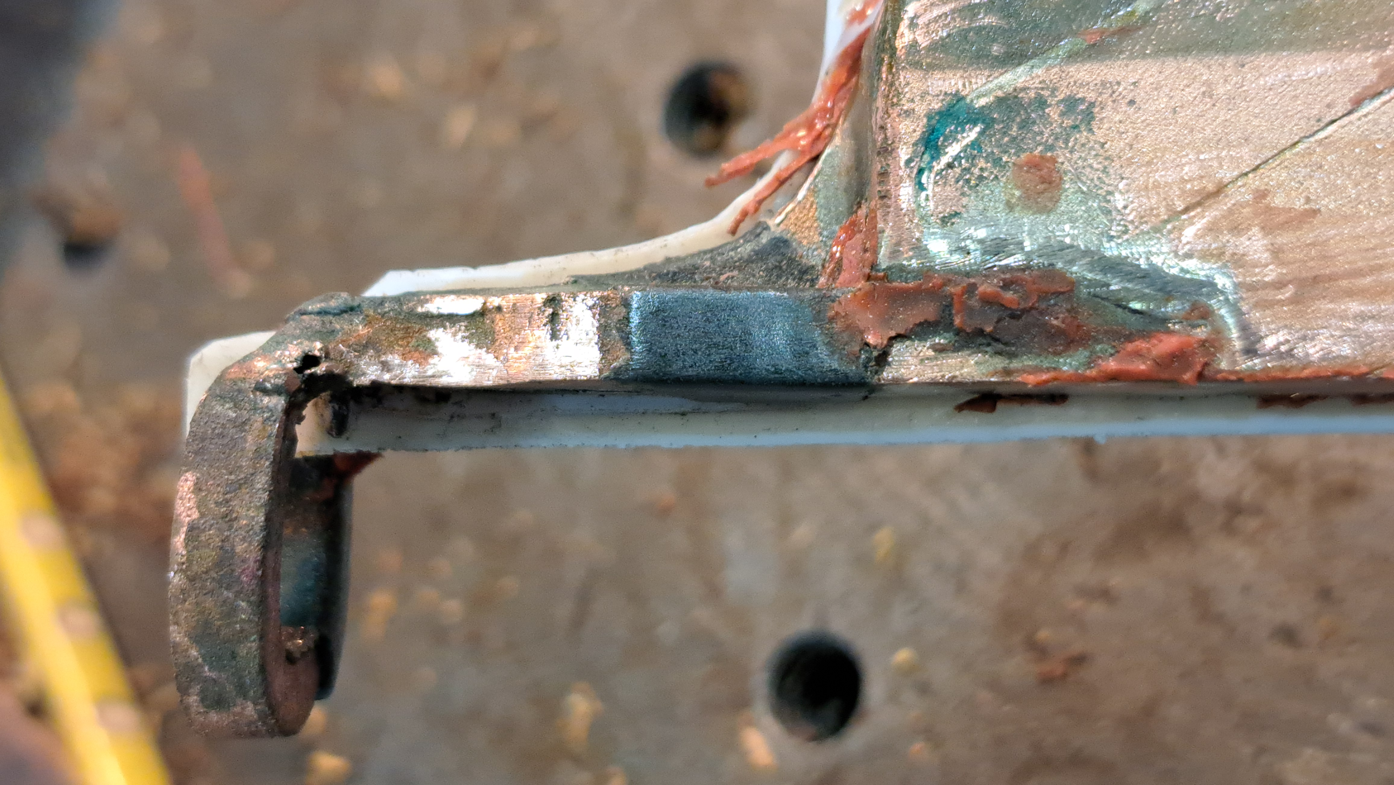
The print called for a slot in the flux concentrator to give the Teflon proper clearance. That slot was not machined. During assembly, the concentrator compressed the Teflon and pushed it deeper into the head.
The insulation no longer protected the critical high-field area. Under power, the coil arced, tracked across the insulation, and failed hard.
Not a rookie mistake. It could happen to anybody. But it still should not happen.
The failed coil
These two photos show the bad head after failure. The first image shows the burnt Teflon pushed deep into the head. The second shows the Teflon cut too far back so it was not sticking out far enough to protect the area it needed to protect.
What actually went wrong
- The print called for a relief slot in the flux concentrator.
- That slot was not machined.
- The concentrator compressed the Teflon during assembly.
- The insulation got pushed deeper into the head.
- The critical area lost protection.
- The coil arced and tracked across the insulation surface.
Why the arc started here
The head opening is one of the worst places to lose insulation control. It carries high electrical stress, tight geometry, and almost no forgiveness.
What the failed build tells us
- Assembly pressure changes parts.
- Critical areas cannot be assumed safe.
- Missing one machined feature upstream can create downstream failure.
- Inspection must include high-risk areas before power.
What should have been controlled
- Relief slot present before assembly.
- Teflon position checked after compression.
- Critical areas protected and stabilized.
- Geometry verified before final assembly.
What correct geometry looks like before assembly


These next photos show proper geometry before final processing. Smooth bends, centered spacing, controlled shape, and no crushed tubing.
What makes this one right
- Smooth bend radius instead of sharp stressed corners.
- No tubing crush at the bend.
- Controlled spacing before final separation.
- Geometry starts correct instead of corrected later.
The real lesson
Coils like this usually fail from stacked-up small mistakes in critical areas.
Good coil building is not just shaping copper. It is thinking ahead through machining, fit-up, insulation, compression, clearance, verification, and machine load.
The best builders are always thinking several steps ahead before the machine ever turns on.
Keep Going
Continue into real-world induction coil failures, brazing methods, repair logic, and application-driven coil design.